METHOD 507.6 HUMIDITY CONTENTS 1. SCOPE ........................................................................................................................................................... 1 1.1 PURPOSE .......................................................................................................................................................... 1 1.2 APPLICATION ................................................................................................................................................... 1 1.3 LIMITATIONS.................................................................................................................................................... 1 2. TAILORING GUIDANCE........................................................................................................................... 1 2.1 SELECTING THE HUMIDITY METHOD ............................................................................................................... 1 2.1.1 EFFECTS OF WARM, HUMID ENVIRONMENTS................................................................................................... 2 2.1.2 SEQUENCE AMONG OTHER METHODS.............................................................................................................. 2 2.2 SELECTING PROCEDURES ................................................................................................................................. 2 2.2.1 PROCEDURE SELECTION CONSIDERATIONS ...................................................................................................... 3 2.2.2 DIFFERENCE BETWEEN PROCEDURES .............................................................................................................. 3 2.3 DETERMINE TEST LEVELS, CONDITIONS, AND DURATIONS.............................................................................. 3 2.3.1 TEST TEMPERATURE - HUMIDITY..................................................................................................................... 3 2.3.2 TEST DURATION............................................................................................................................................... 5 2.3.3 TEST ITEM CONFIGURATION ............................................................................................................................ 7 2.3.4 ADDITIONAL GUIDELINES ................................................................................................................................ 7 2.4 OPERATIONAL CHECKOUT ............................................................................................................................... 7 2.4.1 PROCEDURE I (INDUCED CYCLES B1, B2, OR B3, FOLLOWED BY NATURAL CYCLES B1, B2, OR B3) ............. 7 2.4.2 PROCEDURE II - AGGRAVATED ........................................................................................................................ 7 2.5 TEST VARIATIONS............................................................................................................................................ 7 2.6 PHILOSOPHY OF TESTING ................................................................................................................................. 7 2.6.1 PROCEDURE I - INDUCED (STORAGE AND TRANSIT) CYCLES ........................................................................... 8 2.6.2 PROCEDURE I - NATURAL CYCLES ................................................................................................................. 10 2.6.3 PROCEDURE II - AGGRAVATED CYCLE (FIGURE 507.6-7) .............................................................................. 13 3. INFORMATION REQUIRED................................................................................................................... 14 3.1 PRETEST......................................................................................................................................................... 14 3.2 DURING TEST.................................................................................................................................................15 3.3 POST-TEST .....................................................................................................................................................15 4. TEST PROCESS .........................................................................................................................................15 4.1 TEST FACILITY...............................................................................................................................................15 4.1.1 GENERAL DESCRIPTION ................................................................................................................................. 15 4.1.2 FACILITY DESIGN...........................................................................................................................................15 4.1.3 TEST SENSORS AND MEASUREMENTS ............................................................................................................ 15 4.1.4 AIR VELOCITY ...............................................................................................................................................16 4.1.5 HUMIDITY GENERATION ................................................................................................................................16 4.1.6 CONTAMINATION PREVENTION ......................................................................................................................16 4.2 CONTROLS .....................................................................................................................................................16 4.3 TEST INTERRUPTION ......................................................................................................................................16 4.3.1 INTERRUPTION DUE TO CHAMBER MALFUNCTION.........................................................................................16 4.3.2 INTERRUPTION DUE TO TEST ITEM OPERATION FAILURE...............................................................................17 4.4 TEST EXECUTION ...........................................................................................................................................17 4.4.1 PREPARATION FOR TEST................................................................................................................................. 17 4.4.1.1 TEST SETUP....................................................................................................................................................17 4.4.1.2 PRELIMINARY STEPS ......................................................................................................................................17
4.4.1.3 PRETEST CHECKOUT ......................................................................................................................................17
4.4.2 TEST PROCEDURES.........................................................................................................................................17
4.4.2.1 PROCEDURE I - STORAGE AND TRANSIT CYCLES (CYCLES B2 OR B3), AND NATURAL (CYCLES B1,
B2, OR B3......................................................................................................................................................17
4.4.2.2 PROCEDURE II - AGGRAVATED ......................................................................................................................18
5. ANALYSIS OF RESULTS.........................................................................................................................19
6. REFERENCE/RELATED DOCUMENTS ...............................................................................................19
6.1 REFERENCED DOCUMENTS.............................................................................................................................19
6.2 RELATED DOCUMENTS...................................................................................................................................19
TABLES
TABLE 507.6-I HIGH HUMIDITY DIURNAL CATEGORIES .......................................................................................... 5
TABLE 507.6-II TEST CYCLES (DAYS) ...................................................................................................................... 7
TABLE 507.6-III CONSTANT TEMPERATURE AND HUMIDITY - INDUCED CYCLE B1................................................... 8
TABLE 507.6-IV CYCLIC HIGH RELATIVE HUMIDITY - INDUCED CYCLE B2 .............................................................. 9
TABLE 507.6-V HOT HUMID - INDUCED CYCLE B3................................................................................................. 10
TABLE 507.6-VI CONSTANT TEMPERATURE AND HUMIDITY - NATURAL CYCLE B1................................................11
TABLE 507.6-VII CYCLIC HIGH RELATIVE HUMIDITY - NATURAL CYCLE B2 ...........................................................12
TABLE 507.6-VIII HOT HUMID - NATURAL CYCLE B3................................................................................................13
TABLE 507.6-IX AGGRAVATED CYCLE ....................................................................................................................14
FIGURES
FIGURE 507.6-1 INDUCED CYCLE B1 - STORAGE AND TRANSIT................................................................................. 8
FIGURE 507.6-2 INDUCED CYCLE B2 - STORAGE AND TRANSIT................................................................................. 9
FIGURE 507.6-3 INDUCED CYCLE B3 - STORAGE AND TRANSIT...............................................................................10
FIGURE 507.6-4 NATURAL CYCLE B1 - CONSTANT HIGH HUMIDITY.......................................................................11
FIGURE 507.6-5 NATURAL CYCLE B2 - CYCLIC HIGH HUMIDITY............................................................................12
FIGURE 507.6-6 NATURAL CYCLE B3 - HOT HUMID................................................................................................13
FIGURE 507.6-7 AGGRAVATED TEMPERATURE - HUMIDITY CYCLE ........................................................................14
METHOD 507.6, ANNEX A
PHYSICAL PHENOMENA ASSOCIATED WITH HUMIDITY
1. ABSORPTION .......................................................................................................................................... A-1
2. ADSORPTION .......................................................................................................................................... A-1
3. BREATHING ............................................................................................................................................ A-1
4. CONDENSATION .................................................................................................................................... A-1
5. DIFFUSION............................................................................................................................................... A-1
HUMIDITY
NOTE: Tailoring is essential. Select methods, procedures, and parameter levels based on the
tailoring process described in Part One, paragraph 4.2.2, and Annex C. Apply the general
guidelines for laboratory test methods described in Part One, paragraph 5 of this Standard.
1. SCOPE.
1.1 Purpose.
The purpose of this Method is to determine the resistance of materiel to the effects of a warm, humid atmosphere.
1.2 Application.
This Method applies to materiel that is likely to be stored or deployed in a warm, humid environment, an
environment in which high levels of humidity occur, or to provide an indication of potential problems associated
with humidity. Although it is preferable to test materiel at appropriate natural environment sites, it is not always
practical because of logistical, cost, or schedule considerations. Warm, humid conditions can occur year-round in
tropical areas, seasonally in mid-latitude areas, and in materiel subjected to combinations of changes in pressure,
temperature, and relative humidity. Often materiel enclosed in non-operating vehicles in warm, humid areas can
experience high internal temperature and humidity conditions. Other high levels of humidity can exist worldwide.
Further information on high temperatures and humidity is provided in AR 70-38 (paragraph 6.1, reference a), MILHDBK-310
(paragraph 6.1, reference b), or NATO STANAG 4370, AECTP 230 (paragraph 6.1, reference c). See
also Part Three of this Standard.
1.3 Limitations.
This Method may not reproduce all of the humidity effects associated with the natural environment such as longterm
effects, nor with low humidity situations. This Method does not attempt to duplicate the complex
temperature/humidity environment but, rather, it provides a generally stressful situation that is intended to reveal
potential problem areas in materiel. This Method includes natural and induced temperature/humidity cycles (for
guidance purposes) for identified climatic categories, but these cycles cannot replicate naturally-occurring
environments. Testing in the natural environment, whenever practical, may provide more valuable results.
Specifically, this Method does not address:
a. Condensation resulting from changes of pressure and temperature for airborne or ground materiel.
b. Condensation resulting from black-body radiation (e.g., night sky effects).
c. Synergistic effects of solar radiation, humidity, or condensation combined with biological and chemical
contaminants.
d. Liquid water trapped within materiel or packages and retained for significant periods.
e. Evaluating the internal elements of a hermetically sealed assembly since such materiel is air-tight.
2. TAILORING GUIDANCE.
2.1 Selecting the Humidity Method.
After examining requirements documents and applying the tailoring process in Part One of this Standard to
determine if warm temperature/humidity conditions are anticipated in the life cycle of materiel, use the following to
confirm the need for this Method and to place it in sequence with other methods.
NOTE: Consider the potential synergistic effects of temperature, humidity, and altitude,
and the use of Method 520.4 in addition to this Method. However, Method 520 is NOT a
substitute for Method 507.
2.1.1 Effects of Warm, Humid Environments.
Temperature-humidity conditions have physical and chemical effects on materiel; the temperature and humidity
variations can also trigger synergistic effects or condensation inside materiel. Consider the following typical
problems to help determine if this Method is appropriate for the materiel being tested. This list is not intended to be
all-inclusive.
a. Surface effects, such as:
(1) Oxidation and/or galvanic corrosion of metals.
(2) Increased chemical reactions.
(3) Chemical or electrochemical breakdown of organic and inorganic surface coatings.
(4) Interaction of surface moisture with deposits from external sources to produce a corrosive film.
(5) Changes in friction coefficients, resulting in binding or sticking.
b. Changes in material properties, such as:
(1) Swelling of materials due to sorption effects.
(2) Other changes in properties.
(a) Loss of physical strength.
(b) Electrical and thermal insulating characteristics.
(c) De-lamination of composite materials.
(d) Change in elasticity or plasticity.
(e) Degradation of hygroscopic materials.
(f) Degradation of explosives and propellants by absorption.
(g) Degradation of optical element image transmission quality.
(h) Degradation of lubricants.
c. Condensation and free water, such as:
(1) Electrical short circuits.
(2) Fogging of optical surfaces.
(3) Changes in thermal transfer characteristics.
2.1.2 Sequence Among Other Methods.
a. General. Use the anticipated life cycle sequence of events as a general sequence guide (see Part One,
paragraph 5.5).
b. Unique to this Method. Humidity testing may produce irreversible effects. If these effects could
unrealistically influence the results of subsequent tests on the same item(s), perform humidity testing
following those tests. Also, because of the potentially unrepresentative combination of environmental
effects, it is generally inappropriate to conduct this test on the same test sample that has previously been
subjected to salt fog, sand and dust, or fungus tests. Dynamic environments (vibration and shock) could
influence the results of humidity testing. Consider performing these dynamic tests prior to humidity tests.
2.2 Selecting Procedures
This Method consists of two procedures, Procedure I (Induced (Storage and Transit) and Natural Cycles), and
Procedure II (Aggravated). Determine the procedure(s) to be used.
NOTE: The materiel’s anticipated Life Cycle Environmental Profile (LCEP) may reveal other
scenarios that are not specifically addressed in the procedures. Tailor the procedures as necessary
to capture the LCEP variations, but do not reduce the basic test requirements reflected in the below
procedures. (See paragraph 2.3 below.)
2.2.1 Procedure Selection Considerations.
a. The operational purpose of the materiel.
b. The natural exposure circumstances.
c. Test data required to determine if the operational purpose of the materiel has been met.
d. Test duration.
2.2.2 Difference Between Procedures. (See paragraph 1.3c for related information on limitations.)
a. Procedure I – Induced (Storage and Transit) and Natural Cycles. Once a cycle is selected, perform the storage
and transit portion first, followed by the corresponding natural environment portion of the cycle. Procedure I
includes:
(1) three unique cycles that represent conditions that may occur during storage or transit, as well as
(2) three unique natural environment cycles that are performed on test items that are open to the environment.
The internal humidity may be caused by these or other mechanisms:
(a) Entrapped, highly humid air.
(b) Presence of free water.
(c) Penetration of moisture through test item seals (breathing).
(d) Release of water or water vapor from hygroscopic material within the test item.
b. Procedure II – Aggravated. Procedure II exposes the test item to more extreme temperature and humidity
levels than those found in nature (without contributing degrading elements), but for shorter durations. Its
advantage is that it produces results quickly, i.e., it may, generally, exhibit temperature-humidity effects
sooner than in the natural or induced procedures. Its disadvantage is that the effects may not accurately
represent those that will be encountered in actual service. Be careful when interpreting results. This
procedure is used to identify potential problem areas, and the test levels are fixed.
2.3 Determine Test Levels, Conditions, and Durations.
Related test conditions depend on the climate, duration, and test item configuration during shipping, storage, and
deployment. The variables common to both procedures are the temperature-humidity cycles, duration, and
configuration. These variables are discussed below. Requirements documents may impose or imply additional test
conditions. Otherwise, use the worst-case conditions to form the basis for selecting the test and test conditions to use.
2.3.1 Test Temperature - Humidity.
The specific test temperature - humidity values are selected, preferably, from the requirements documents. If this
information is not available, base determination of the test temperature-humidity values for Procedure I on the world
geographical areas in which the test item will be used, plus any additional considerations. Table 507.6-I was
developed from AR 70-38 (paragraph 6.1, reference a), MIL-HDBK-310 (paragraph 6.1, reference b), NATO
STANAG 4370 (paragraph 6.1, reference d), AECTP 200 (paragraph 6.1, reference e), and NATO STANAG 4370,
AECTP 230 (paragraph 6.1, reference c, (part three)) and includes the temperature and relative humidity conditions
for three geographical categories where high relative humidity conditions may be of concern, and three related
categories of induced conditions. The temperature and humidity data are those used in the source documents
mentioned above. The cycles were derived from available data; other geographic areas could be more severe. For
Procedure I, the temperature and humidity levels in Table 507.6-I are representative of specific climatic areas; the
natural cycles are not adjustable. Figures 507.6-1 through 507.6-6 are visual representations of the cycles in Table
507.6-I.
Although they occur briefly or seasonally in the mid-latitudes, basic high humidity conditions are found most often
in tropical areas. One of the two high humidity cycles (constant high humidity) represents conditions in the heavily
forested areas where nearly constant conditions may prevail during rainy and wet seasons. Exposed materiel is
likely to be constantly wet or damp for many days at a time. A description of each category follows.
a. Constant high humidity (Cycle B1). Constant high humidity is found most often in tropical areas, although it
occurs briefly or seasonally in the mid-latitudes. The constant-high-humidity cycle represents conditions in
heavily forested areas where nearly constant temperature and humidity may prevail during rainy and wet
seasons with little (if any) solar radiation exposure. Tropical exposure in a tactical configuration or mode is
likely to occur under a jungle canopy. Exposed materiel is likely to be constantly wet or damp for many days
at a time. World areas where these conditions occur are the Congo and Amazon Basins, the jungles of Central
America, Southeast Asia (including the East Indies), the north and east coasts of Australia, the east coast of
Madagascar, and the Caribbean Islands. The conditions can exist for 25 to 30 days each month in the most
humid areas of the tropics. The most significant variation of this cycle is its frequency of occurrence. In
many equatorial areas, it occurs monthly, year round, although many equatorial areas experience a distinctive
dry season. The frequency decreases as the distance from the equator increases. The mid-latitudes can
experience these conditions several days a month for two to three months a year. See Part Three for further
information on the description of the environments.
b. Cyclic high humidity (Cycle B2). Cyclic high humidity conditions are found in the open in tropical areas
where solar radiation is a factor. If the item in its operational configuration is subject to direct solar radiation
exposure, it is permissible to conduct the natural cycle with simulated solar radiation. See Part Three, Table
VII, for the associated B2 diurnal solar radiation parameters. In these areas, exposed items are subject to
alternate wetting and drying, but the frequency and duration of occurrence are essentially the same as in the
constant high humidity areas. Cycle B2 conditions occur in the same geographical areas as the Cycle B1
conditions, but the B1 conditions typically are encountered under a jungle canopy, so the B1 description
above also applies to the B2 area.
c. Hot-humid (Cycle B3). Severe (high) dewpoint conditions occur 10 to 15 times a year along a very narrow
coastal strip, probably less than 5 miles wide, bordering bodies of water with high surface temperatures,
specifically the Persian Gulf and the Red Sea. If the item in its operational configuration is subject to direct
solar radiation exposure, it is permissible to conduct the natural cycle with simulated solar radiation. See Part
Three, Table V for the associated B3 diurnal solar radiation parameters. Most of the year, these same areas
experience hot dry (A1) conditions. This cycle is unique to materiel to be deployed specifically in the Persian
Gulf or Red Sea regions, and is not to be used as a substitute for worldwide exposure requirements where B1
or B2 would apply.
In addition to these three categories of natural high-humidity conditions, there are three cycles for induced (storage and
transit) conditions:
d. Induced constant high humidity (Cycle B1). Relative humidity above 95 percent in association with nearly
constant 27 qC (80 qF) temperature occurs for periods of a day or more.
e. Induced variable - high humidity (Cycle B2). This condition exists when materiel in the
variable-high-humidity category receives heat from solar radiation with little or no cooling air. See storage
and transit conditions associated with the hot-humid daily cycle of the hot climatic design type below in
Table 507.6-I.
f. Induced hot-humid (Cycle B3). This condition exists when materiel in the hot-humid category receives heat
from solar radiation with little or no cooling air. The daily cycle for storage and transit in Table 507.6-I
shows 5 continuous hours with air temperatures at or above 66 qC (150 qF), and an extreme air temperature
of 71 qC (160 qF) for not more than 1 hour.
Table 507.6-I. High humidity diurnal categories.
Time
Natural1 Induced (Storage and Transit)
High Humidity
Hot Humid
(Cycle B3)
Constant
Temp.
(Cycle B1)
Cyclic High
RH
(Cycle B2)
Hot Humid
(Cycle B3)
Constant
Temp.
(Cycle B1)
Cyclic High
RH
(Cycle B2)
Temp RH Temp RH Temp RH Temp RH Temp RH Temp RH
o
C o
F % o
C o
F % o
C o
F % o
C o
F % o
C o
F % o
C o
F %
0100
Nearly constant at 24oC (75oF) throughout the 24 hours
1002 27 80 100 31 88 88
Nearly constant at 27oC (80oF) throughout the 24 hours
100 33 91 69 35 95 67
0200 100 26 79 100 31 88 88 100 32 90 70 34 94 72
0300 100 26 79 100 31 88 88 100 32 90 71 34 94 75
0400 100 26 79 100 31 88 88 100 31 88 72 34 93 77
0500 100 26 78 100 31 88 88 100 30 86 74 33 92 79
0600 100 29 78 100 32 90 85 100 31 88 75 33 91 80
0700 98 27 81 94 34 93 80 98 34 93 64 36 97 70
0800 97 29 84 88 36 96 76 97 38 101 54 40 104 54
0900 95 31 87 82 37 98 73 95 42 107 43 44 111 42
1000 95 32 89 79 38 100 69 95 45 113 36 51 124 31
1100 95 33 92 77 39 102 65 95 51 124 29 57 135 24
1200 95 34 94 75 40 104 62 95 57 134 22 62 144 17
1300 95 34 94 74 41 105 59 95 61 142 21 66 151 16
1400 95 35 95 74 41 105 59 95 63 145 20 69 156 15
1500 95 35 95 74 41 105 59 95 63 145 19 71 160 14
1600 95 34 93 76 41 105 59 95 62 144 20 69 156 16
1700 95 33 92 79 39 102 65 95 60 140 21 66 151 18
1800 95 32 90 82 37 99 69 95 57 134 22 63 145 21
1900 97 31 88 86 36 97 73 97 50 122 32 58 136 29
2000 98 29 85 91 34 94 79 98 44 111 43 50 122 41
2100 100 28 83 95 33 91 85 100 38 101 54 41 105 53
2200 100 28 82 96 32 90 85 100 35 95 59 39 103 58
2300 100 27 81 100 32 89 88 100 34 93 63 37 99 62
2400 100 27 80 100 31 88 88 100 33 91 68 35 95 63
1 Temperature and humidity values are for ambient air.
2 For chamber control purpose, 100 percent RH implies as close to 100 percent RH as possible, but not less than 95 percent.
2.3.2 Test Duration.
The number of temperature - humidity cycles (total test time) is critical in achieving the purpose of the test. The
durations provided in Table 507.6-II are minimum durations and, in most cases, are far less than necessary to provide
an annual comparison. Apply the number of test cycles on a one-for-one basis, i.e., 45 cycles equates to 45 days in the
natural environment, and is not related to any acceleration factor. For Procedure I, see Table 507.6-II and use the
storage and transit durations for the appropriate cycle (B1, B2, or B3), followed by the corresponding natural cycle
duration. For Procedure II guidance, see paragraph 2.3.2c below.
NOTE: During or after this test, document any degradation that could contribute to failure of the test
item during more extensive exposure periods (i.e., indications of potential long term problems), or
during exposure to other deployment environments such as shock and vibration. Further, extend testing
for a sufficient period of time to evaluate the long-term effect of its realistic deployment duration
(deterioration rate becomes asymptotic).
a. Procedure Ia - Induced (Storage and Transit) Cycles
(1) Hazardous test items. Hazardous test items will generally require longer tests than nonhazardous items to
establish confidence in test results. Since induced conditions are much more severe than natural
conditions, potential problems associated with high temperature/high relative humidity will be revealed
sooner, and the results can be analyzed with a higher degree of confidence. Consequently, expose
hazardous test items to extended periods (double the normal periods) of conditioning, depending upon the
geographical category to which the materiel will be exposed (see Table 507.6-II, induced cycles B1
through B3).
(2) Non-hazardous test items. Induced conditions are much more severe than natural conditions, and
potential problems associated with high temperature/high humidity will thus be revealed sooner, and the
results can be analyzed, in most cases, with a higher degree of confidence. Expose non-hazardous test
items to test durations as specified in Table 507.6-II, induced cycles B1 through B3, depending upon the
geographical category to which the material will be exposed.
b. Procedure Ib - Natural Cycles
(1) Hazardous test items. Hazardous test items are those in which any unknown physical deterioration
sustained during testing could ultimately result in damage to materiel or injury or death to personnel
when the test item is used. Hazardous test items will generally require longer test durations than
nonhazardous test items to establish confidence in the test results. Twice the normal test duration is
recommended (see Table 507.6-II, cycles B1 through B3).
(2) Nonhazardous test items. Nonhazardous test items should be exposed from 15 to 45 cycles of
conditioning, depending upon the geographical area to which the materiel will be exposed (see Table
507.6-II, cycles B1 through B3).
NOTE: The climate station selected for these categories was Majuro, Marshall Islands (7o
05’ N,
171o
23’E). The station is located at the Majuro Airport Weather Services building. This site is a firstorder
U.S. weather reporting station. Majuro was selected over 12 available candidate stations from
around the world initially because it possessed the required temperature and precipitation characteristics
for the B1 category (resulting in high temperature – humidity conditions), and it met the criteria for data
availability and quality.
On the average, Majuro receives over 3,300 mm (130 inches) of rainfall annually. Over 250 days
experience rainfall >= 0.01 inch, and over 310 days experience rainfall >= trace. Ten years of continuous
data were used for the analysis (POR: 1973-1982).
Groupings of consecutive days of rainfall (and resulting humidity) were then extracted. The longest
continuous streak of consecutive days >= trace was 51. A cumulative frequency curve was then created.
The recommended duration value of 45 days represents the 99th percentile value (actual value = 98.64%)
Table 507.6-II. Test cycles (days).
MATERIEL
CATEGORY
NATURAL INDUCED (STORAGE and TRANSIT)
Cycle B1 Cycle B2 Cycle B3 Cycle B1 Cycle B2 Cycle B3
Hazardous Items
Normal Test Duration
90 90 30 180 180 30
Non-Hazardous Items
Normal Test Duration 1 45 45 15 90 90 15
1
Perform operational checks at least once every five days; more frequent checks may provide early detection of potential
problems.
c. Procedure II – Aggravated Cycle. For Procedure II, in addition to a 24-hour conditioning cycle (paragraph
4.4.2.2), the minimum number of 24-hour cycles for the test is ten. Although the combined 60 qC (140 qF)
and 95 percent RH does not occur in nature, this combination of temperature and relative humidity, has
historically proven adequate to reveal potential effects in most materiel. Extend the test as specified in the
test plan to provide a higher degree of confidence in the materiel to withstand warm, humid conditions. For
the test items incorporating seals to protect moisture-sensitive materials, e.g., pyrotechnics, longer test
durations may be required.
2.3.3 Test Item Configuration. During conduct of the temperature-humidity procedures of this Method, configure
the test item as specified below, or as specifically outlined in the requirements documents. Test item configuration
must be selected to reproduce, as closely as technically possible, the configuration that the test item would assume
when worst-case situations are encountered during its life cycle.
a. In its assigned shipping/storage container, or as installed in the end item.
b. Out of its shipping/storage container but not set up in its deployment mode.
c. In its operational mode (realistically or with restraints, such as with openings that are normally covered).
2.3.4. Additional Guidelines. Review the requirements documents. Apply any additional guidelines necessary.
2.4 Operational Checkout.
2.4.1 Procedure I (Induced Cycles B1, B2, or B3, Followed By Natural Cycles B1, B2, or B3)
a. Procedure Ia: Induced (storage and transit) cycles B1, B2, and B3 represent storage and transit
environments. As such, perform operational checkouts before and after each test.
b. Procedure Ib: Natural cycles B1 - B3 represent the operational environment, and, theoretically, the
materiel could be functioning non-stop in the natural environment. In this case, operate the test item
continuously throughout the test procedure. If shorter operational periods are identified in the requirements
document(s), operate the test item at least once every five cycles for a duration necessary to verify proper
operation. This operational checkout will help determine effects of the natural cycles on test item(s) as
soon as possible.
2.4.2 Procedure II - Aggravated.
Procedure II does not represent naturally-occurring conditions; therefore it may produce an acceleration of potential
temperature-humidity effects. If the test item is intended to be operated in a warm, humid environment, perform at
least one operational checkout every five cycles during the periods shown on Figure 507.6-7.
2.5 Test Variations.
The most important ways the tests can vary are in the number of temperature-humidity cycles, relative humidity, and
temperature levels and durations, test item performance monitoring (where appropriate), and test item ventilation.
2.6 Philosophy of Testing.
Procedures Ia and Ib are intended to reveal representative effects that typically occur when materiel is exposed to
elevated temperature-humidity conditions in storage and transit, followed by actual service where moderate to high


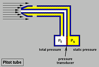
 và một phần chất lỏng chuyển động song song với miệng ống được dùng để đo áp suất tĩnh
  (màu vàng).

 tồn tại trong phương trình (1) được gọi là áp suất động. Từ phương trình (1), ta rút ra được vận tốc như sau:
}}{\rho }} }")
 . Xác định vận tốc của máy bay?
 và cũng là áp suất tĩnh
  . Từ công thức (), vận tốc của máy bay được xác định như sau:
}}{\rho }} = \sqrt {\frac{{2\left( {1.049 - 1.01325} \right) \times {{10}^5}}}{{1.225}}} \approx {\rm{76}}{\rm{.4}}{m}/{s}}")
 . Tại một vị trí trên cánh máy bay, vận tốc đo được là
  . Hãy xác định:
}}{\rho }} = \sqrt {\frac{{2\left( {1.07 - 1.01325} \right) \times {{10}^5}}}{{1.225}}} \approx {\rm{96}}{\rm{.25}}m/s}")


 , vector chuyển dời
  , vector vị trí
  , và vector vị trí
  tại thời điểm t = 0 có các thành phần trong hệ tọa độ Đề Các lần lượt như sau:


 và
và  trong biểu thức trên sẽ xác định các đường dòng khác nhau trong trường dòng tại mỗi thời điểm t. Nghĩa là ứng với mỗi cặp hệ số này ta có một đường dòng tương ứng. Còn tham số s xác định vị trí của điểm trên đường dòng.
  ,
,  , và
, và  . Thay vào các phương trình trên ta được:


 trên mặt phẳng z = 0.


 . Từ kết quả trong cơ học chất lỏng, ta có được profile vận tốc phân bố tuyến tính giữa hai tấm phẳng.


 ).
). đi qua điểm cố định. Để hiểu rõ hơn, ta thực hiện thí dụ dưới đây.
 , hạt lỏng đi qua điểm A(1,1,0) cho nên ta có được:


